
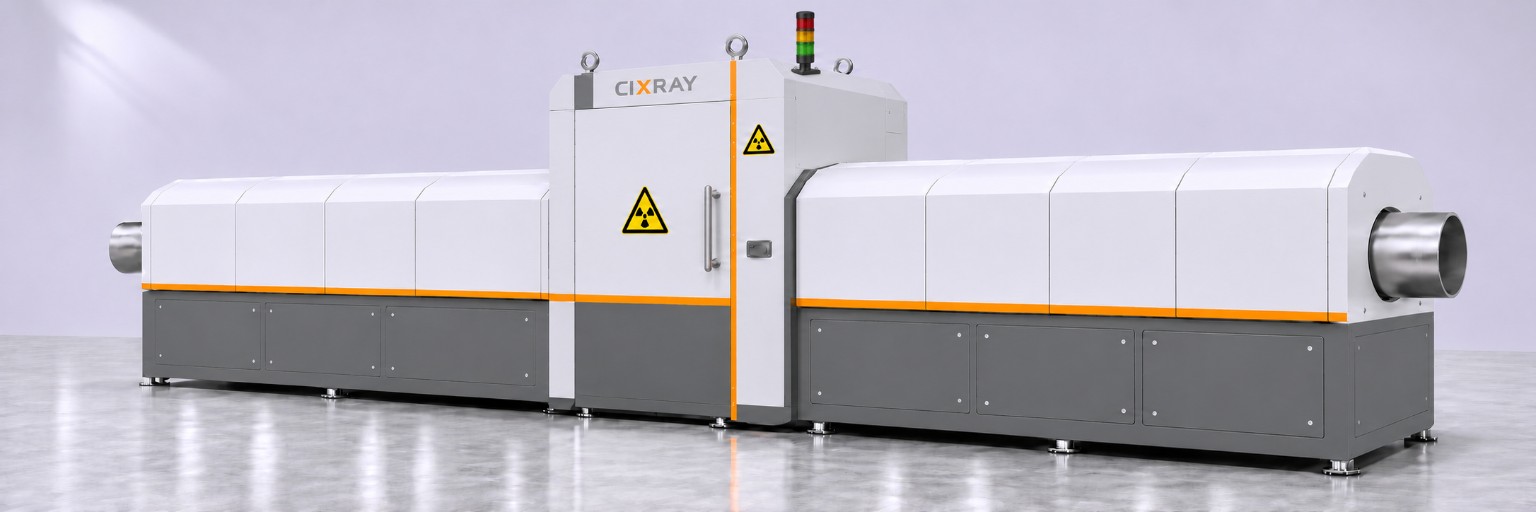
Equipment and application
V-rollers feed and support the pipe. The system rotates the pipe to align the longitudinal seam and captures digital radiographs in steps. The design diameter range is 150–508 mm. Wall thickness and acceptance conditions are confirmed for each project.
Equipment layout
- Two conveyor sections feed the central inspection cabinet. The X-ray source is below the pipe and the flat-panel detector is above it.
- Pipe support, positioning and shielding are configured to suit the pipe sizes and installation conditions.
For equipment selection and sample testing
Pipe material, diameter, thickness, length, seam location, inspection standard and line cycle time.
Configuration and performance depend on the selected model, workpiece and sample testing.
Step-by-step inspection
- Load and position
V-rollers support and feed the pipe into the inspection channel.
- Align the seam
Rotate the pipe until the longitudinal weld reaches the designated imaging position.
- Acquire images in steps
Advance the pipe axially and stop at each exposure position. Set the step distance to suit the imaging coverage and required overlap.
- Review the images
Review radiographs by pipe and scan position using the agreed acceptance criteria.
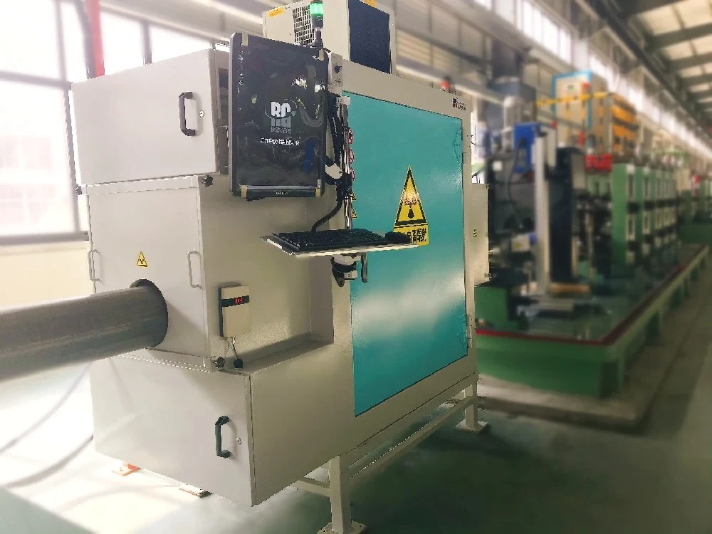
Inline Welded Pipe X-ray Inspection
Acquire radiographic weld images on a welded pipe production line. Select acquisition parameters by tube material, wall thickness and line speed. A defect position marking interface can be evaluated.
For equipment selection and sample testing
Pipe diameter, material, wall thickness, welding speed and marking requirements.
Configuration and performance depend on the selected model, workpiece and sample testing.